Union's 2000 Concrete
Canoe
- PRELIMINARY WORK
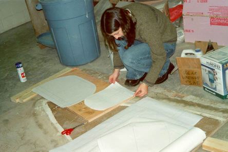
- 1. 1 foot stations were plotted, then attached to
plywood. These would become the cross sections of the
canoe.
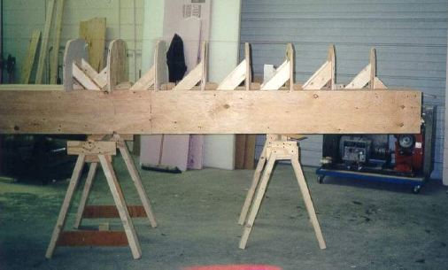
- 2. The plywood cross sections were attached to the
strongback
- 3. 2 by 4's were used to hold the sections to the
strongback
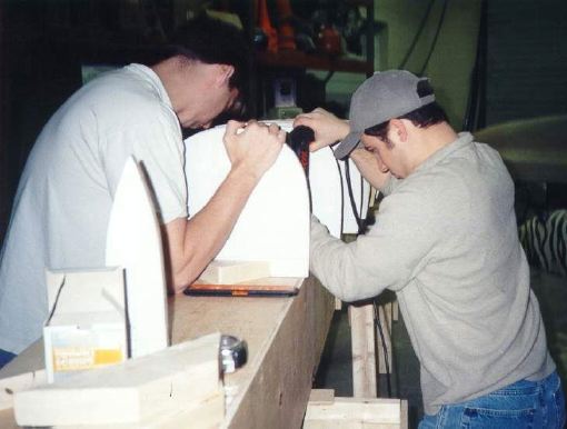
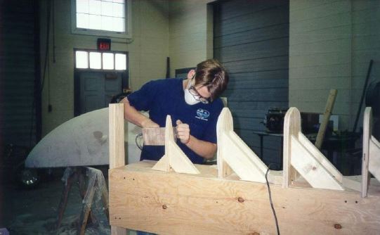
- 4. Care was taken to insure the sections were straight
- 5. By sanding the sections the desired shape was
achieved, and bumps were smoothed
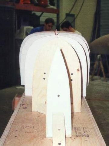
- 6. Wood strips were stapled to the cross sections to
complete the male mold
- 7. The canoe was stripped in three sections, with the bow
and stern section completed first.
- 8. Then the middle third of the canoe was stripped
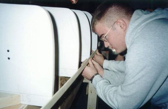
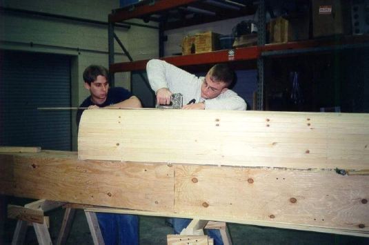
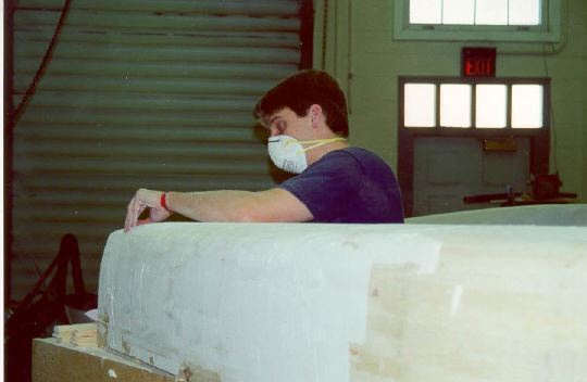
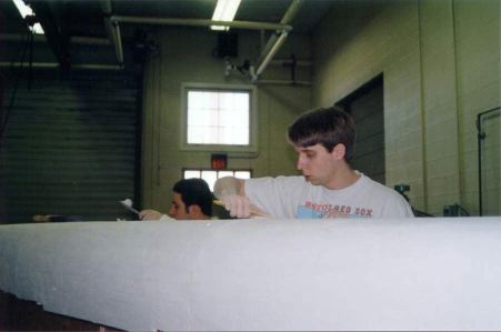
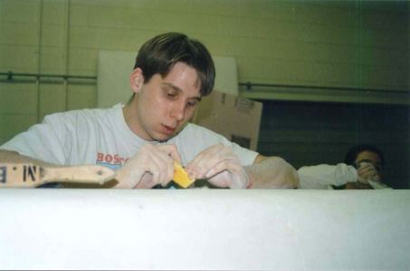
- 9. Many measures were taken in order to obtain a smooth
interior and exterior surface. The strips were sanded and
planed
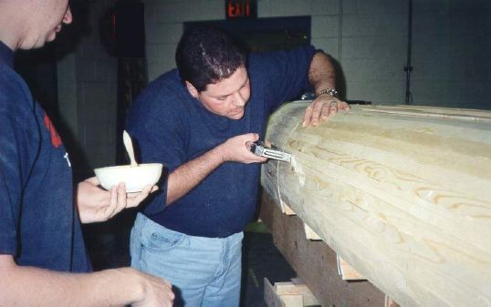
- 10. Then dry wall compound was applied to the mold to
fill in spaces and create a smooth surface.
- 11. In order to make sure the take down mold would come
apart, cuts were made in the dry wall compound layer to
separate the three individual pieces.
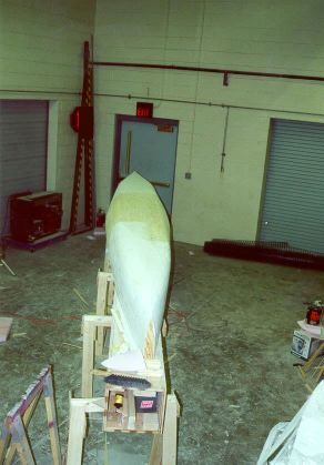
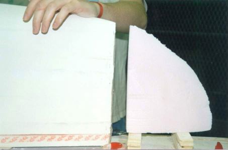
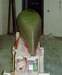
- 12. Foam was placed at the bow and stern to complete the
shape of the canoe.
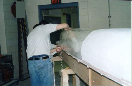
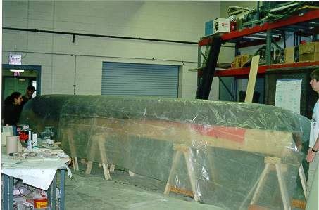
- 13. Shrink-wrap was used to keep the concrete from
bonding to the mold
- 14. This also helped to smooth the interior canoe surface
- 15. Steel wire mesh was used as the primary support for
the canoe. No spacers were used. Instead the mesh was
held to the mold with nails that were extracted during
the pour.
-
- CONCRETE
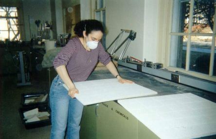
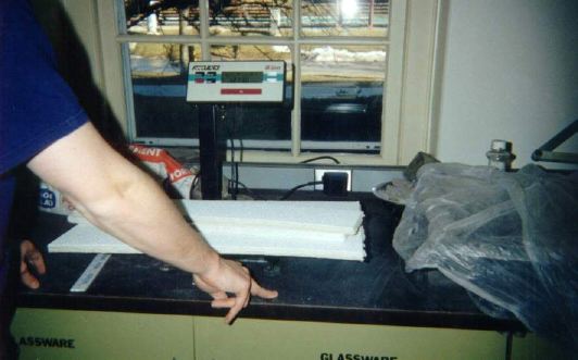
- 16. Ceiling tiles were used as the main aggregate. The
day before they were weighed out by batch...
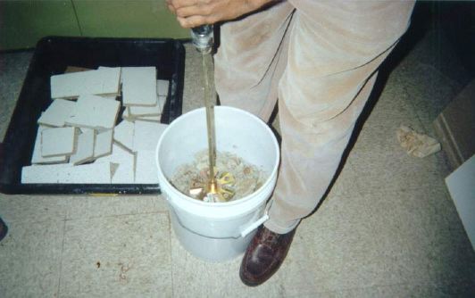
- 17. The ceiling tiles were then broken up into smaller
pieces and soaked for one hour.
- 18. The tiles were then pulped and placed in plastic bags
in order to retain moisture. By doing this the next day's
process of pouring the canoe was more efficient.
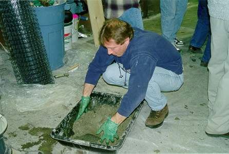
- 19. Batches were made on the day of the pour from the
pre-pulped ceiling tiles, and the cement, which had also
been weighed the day before.
-
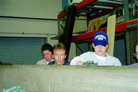
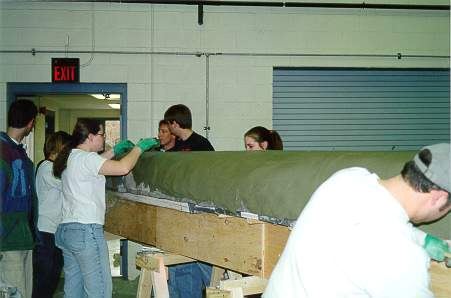
- CANOE CONSTRUCTION
- 20. Union's ASCE members volunteered to help the on day
of the pour.
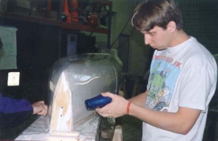
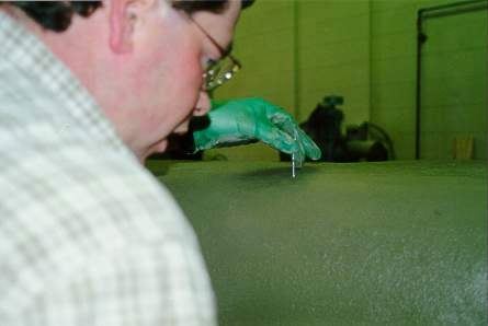
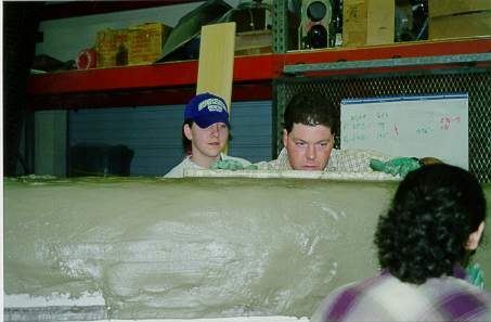
- 21. The pour began at the bow of the canoe, by forcing
the concrete through the steel wire mesh. The three hour
process of pouring the canoe slowly moved toward the
stern.
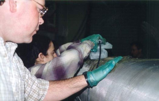
- 22. A vibratory sander was used to help force the
concrete through the steel mesh.
- 23. Wires were cut and marked in order to insure the
thickness remained uniform throughout the canoe
- 24. A pipe was used to smooth out the exterior surface of
the canoe before the final mesh was placed.
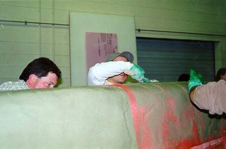
- 25. When the canoe reached it's desired thickness a layer
of fiberglass mesh was placed to complete the double
layer system.
- 26. A very thin layer of concrete covered the fiberglass
mesh in order to create a smooth hull surface.
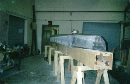
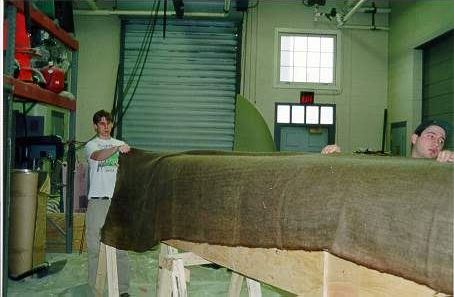
- 27. The canoe was then wrapped in wet burlap, which was
re-soaked on a daily basis. This allowed the canoe to
hydrate.
- 28. A plastic sheet was placed over the burlap to reduce
evaporation. The canoe was allowed 2 weeks to hydrate
before preparation for finishing began.
-
- FINISH & PRACTICE
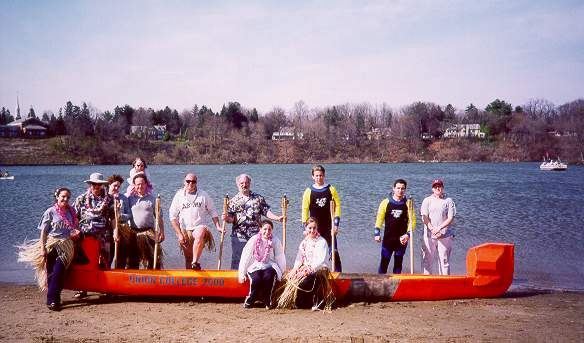
- 29. Floatation was added for two reasons, First – it
allowed the canoe to pass the swamp test at the
competition since the unit weight of the concrete is not
less than that of water. Second – It allowed for a
Polynesian look.
- 30. The canoe was then painted to resemble a tropical
sunset.
-
Please direct all comments, suggestions, and
queries about this page to CE-Webmaster
 Civil
Engineering History Homepage
Civil
Engineering History Homepage