

Our goals were to achieve a better finish on the hull and reduce the overall weight. Last year we encountered difficulty in working the concrete through the mesh, creating gaps over the surface. This year we provided a wire mesh that allowed the concrete to pass completely through the mesh, providing a smooth overall finish. To reduce the weight of the canoe we reduced the freeboard on a fifteen foot length starting at the aft. This was done by securing a 2" strip of plywood to the inside of the mold. The reduced weight is estimated to be 140 pounds. A female mold should theoretically produce a more uniform finish on the outside of the hull that will require less sanding and patching after the canoe is removed from the mold.
The female mold has a 8 inch square grid mapped
inside it. Holes were drilled at the intersecting points on the
grid. These are used to tie the reinforcing to the mold. The tie
wire used is 20 gauge. To accurately position the primary
reinforcement in the mold, one- eighth inch spacers were cut from
one of our basic concrete mix design test cylinders. 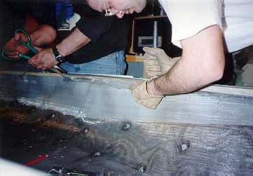 Reinforcement for the gunwale was then secured to the
female mold using the one-eighth inch spacers and the 20 gauge
tie wire. To provide extra lateral support, ceiling grid wire was
secured to the wire mesh laterally every two lee;. This was done
by using 20 gauge tie wire. Reinforcement for the thwart was made
of the secondary reinforcement material. The thwart was formed
using a wooden jig that was placed at the widest point of the
canoe. The ceiling grid was used to reinforce the thwart. First
the wire was wrapped around the inside of the canoe laterally. It
should be noted that the ceiling grid wire was placed on top of
the wire mesh and secured using the 20 gauge tie wire. A
turnbuckle was used to create tension in these wires. The
turnbuckle was placed in the middle of the thwart and was spaced
off the bottom of the thwart mold. Separate pieces of ceiling
grid wire were strung through the thwart form and the ends were
spread out diagonally at a length of about 4 feet. The secondary
reinforcement was tied into place with 20 gauge tie wire during
the casting process.
Reinforcement for the gunwale was then secured to the
female mold using the one-eighth inch spacers and the 20 gauge
tie wire. To provide extra lateral support, ceiling grid wire was
secured to the wire mesh laterally every two lee;. This was done
by using 20 gauge tie wire. Reinforcement for the thwart was made
of the secondary reinforcement material. The thwart was formed
using a wooden jig that was placed at the widest point of the
canoe. The ceiling grid was used to reinforce the thwart. First
the wire was wrapped around the inside of the canoe laterally. It
should be noted that the ceiling grid wire was placed on top of
the wire mesh and secured using the 20 gauge tie wire. A
turnbuckle was used to create tension in these wires. The
turnbuckle was placed in the middle of the thwart and was spaced
off the bottom of the thwart mold. Separate pieces of ceiling
grid wire were strung through the thwart form and the ends were
spread out diagonally at a length of about 4 feet. The secondary
reinforcement was tied into place with 20 gauge tie wire during
the casting process.
The concrete was mixed in batches containing 20
lbs. of portland type I cement. All concrete was placed using a
standard masons trowel A rubber mallet was used on the outside of
the mold to help consolidate the concrete.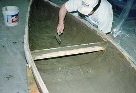
Last years canoe was very thick. so controlling the thickness was
a priority. In order to ensure that the concrete was of uniform
thickness., a trowel was used to screed the concrete to a depth
such that the lateral ceiling grid wire was barely exposed. The
result of this procedure helped to control the thickness of the
canoe, thus reducing the overall weight of our canoe.
The boat was cured by draping it in moistened
burlap and then covering it in plastic to hold the moisture in.
The moistened burlap was left in the canoe for 28 days. Water was
added each day for the first 7 days to keep the canoe moist
during the initial curing.
When removed from the mold, we found that the finish of the
outside of the hull was indeed of higher quality than last years
boat. Some minor defects in the outside surface were filled with
grout. Grout was used to fill in the air voids that were present
on the surface. This was smoothed out using a rubber trowel. The
partially dried grout was then sanded down to a smooth finish.
The high spots on the inside of the canoe were sanded down using
finishing stones. At this point, the canoe was ready for
painting. Last year we considered placing the boat in a muriatic
acid wash to reduce alkalinity of the concrete, but decided that
this was probably not necessary. This year, however, we decided
to use the acid. Two coats of black exterior semi-gloss latex
paint were applied. This was done instead of using the Velspar
Block Primer, which was used last year.
Click here for pictures of construction.
Please direct all comments, suggestions, and queries about this page to CE-Webmaster